Part 1 - Hacking a Motorized Toy for Motor Control - Proof of Concept
- Apr 2, 2018
- 5 min read
The objective of this project, is to prove, using easy-to-implement hardware and software, how to hack a motorized toy and control the motor in a step-by-step format. The final objective will be to utilize an analog sensor to control motor speed.
Part 1: Proof of Concept
Part 2: Hardware Upgrade
Part 3: Rebuild, Use, and Further Work
Proof of Concept
The objective of "Part 1: Proof of Concept" is to demonstrate the basic functionality of the original toy, using simple hardware that easily shows how the motor can be controlled and exactly how that control happens, before downsizing the hardware in part 2.
Why might we go through this process if we know we are going to change the hardware anyway? This process is referred to in the engineering world as the iterative process. Rather than attempting a complicated approach all in one go, the iterative process has you build a simple design that works, and build the more complex processes upon the simple one. By using more basic hardware to prove our concept will work, we can better spec out the parts we will need, make any adjustments along the way with relative ease, and develop a firmer understanding of how the assembly works.
Materials Needed
The following materials are needed for the proof of concept. Note that none of these materials are truly necessary for the final product, but are used only in Part 1 to prove the idea behind the motor control.

Really Annoying Motorized Toy
Wire Snips and Strippers
Screwdrivers (as needed for disassembly)
Small Phillips Head Screwdriver for Motor Shield
Adafruit Motor Shield Featherwing with Male Headers
Adafruit Feather Board with Stacking Headers (I used ESP8266 because I had it laying around, but any will work)
9V Battery with Holder or Connector with Leads
Male-Male Jumper Wires
Pushbutton
Breadboard (optional)
Skills Needed
The best part about this approach is that we can prove this idea will work without any permanent assembly, which means easy and fast.
If not ordered pre-assembled, the stacking headers will need to be soldered to the Feather board and the male headers soldered to the Featherwing. If a refresher on through-hole soldering is needed, check out this post on through-hole soldering with a PCB.
Computing wise the project requires a good understanding of using the operating system and an intermediate understanding of Arduino.
Step 1: Remove / Expose the Mechanical Assembly
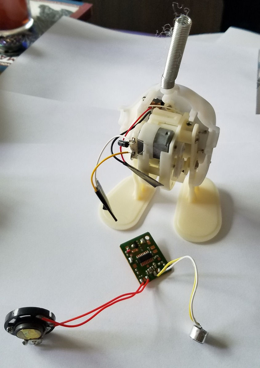
Remove the fur and stuffing from the mechanical assembly, and use a screwdriver if necessary to open the casing. In my case, there were a black and red wire from the battery for power, white and yellow wires from the motor, a small PCB controller which were connected to a speaker and microphone.
I cut the board from the main body by snipping the power and motor wires as close to the board as possible and discard the board, speaker, and microphone assembly.
The black tape is just electrical tape I placed over the ends of the wires after I stripped them to protect them when I wasn't working on the project.
Place electrical tape over the battery wires to protect them. Strip the ends of the motor wire about 1/3 inch.
Step 2: Attaching the Motor Control Test Hardware
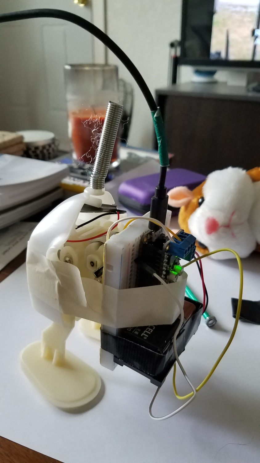
Place the Motor Shield Featherwing on to the Feather. I arranged mine on to the breadboard so that it could also accomodate the test battery and push button.
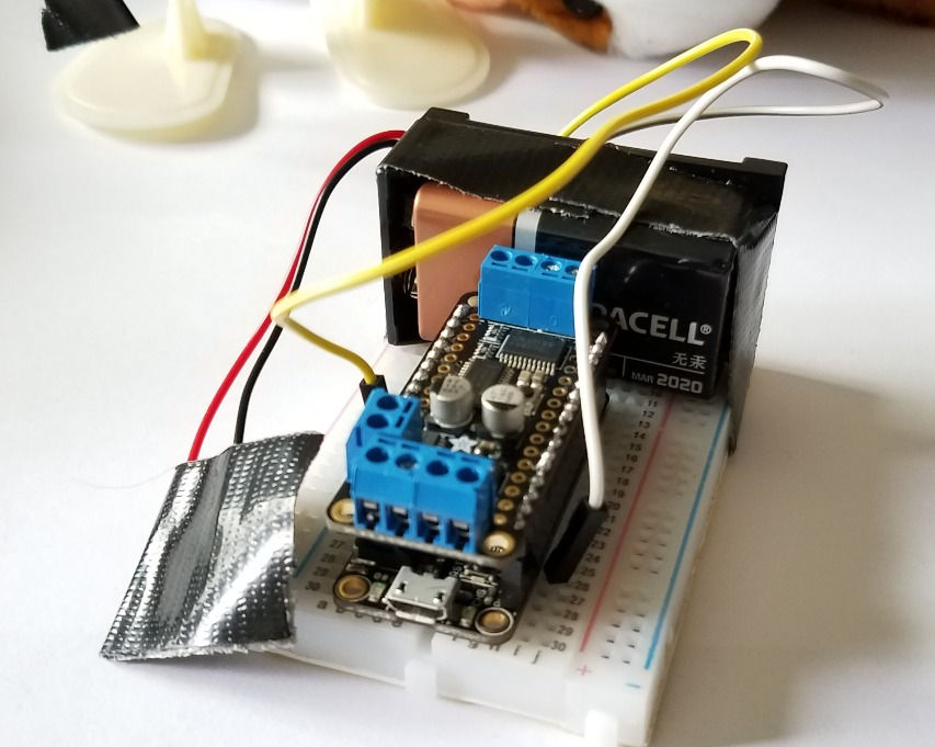
Place the pushbutton into the breadboard and connect one jumper wire to ground and the other to pin 12 (or any pin that has an internal pull-up resistor) as seen below.

The reason we have to use a pin with an internal pull-up resistor is so that the pin is pulled high when not pressed, and pulled low when it is pressed. Without the internal pull-up, the wiring of the button as is would not indicate a change of voltage when pressed. To see which pins of your Feather, or other microcontroller, have internal pull-ups, consult the pinout for the board.
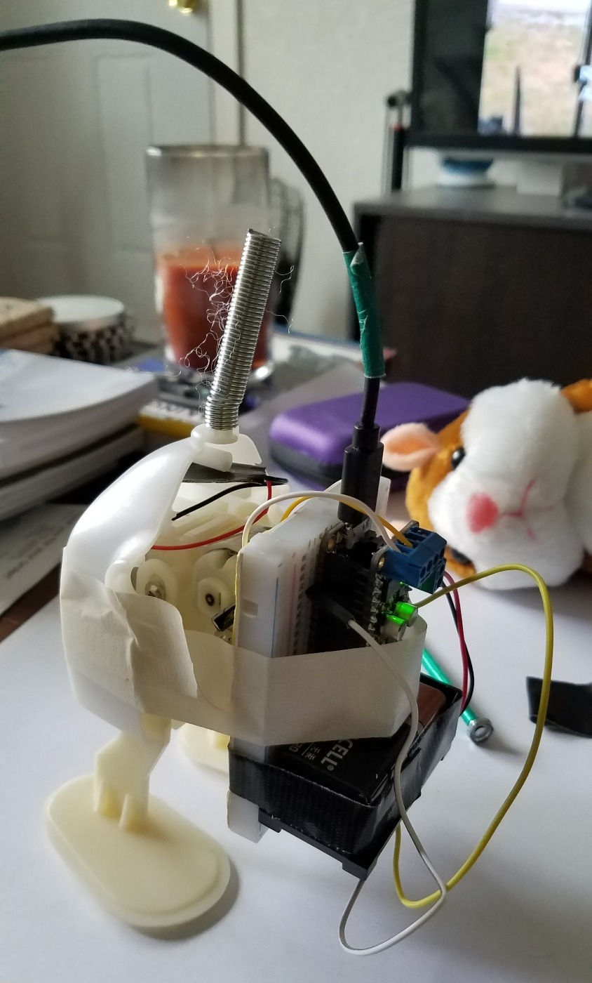
Using a small phillips head screw driver, attach the 9V battery power to the power terminal block, and the motor wires to the M2 motor terminal block. I then used a bit of masking tape to hold the assembly to the toy body.
Step 3: Loading the Code
To load the code, connect the micro USB cord to the Feather and then to the computer and open the Arduino IDE.
The following library needs to be installed:
Adafruit_Motorshield.h
You will also need to download the board manager for the particular board you are using.
Let's walk through the code step-by-step.
First, all libraries we need are to be included
Next, we will set up the motor object using the definitions from the motor shield library.
// Create the motor shield object with the default I2C address Adafruit_MotorShield AFMS = Adafruit_MotorShield(); // Or, create it with a different I2C address (say for stacking) // Adafruit_MotorShield AFMS = Adafruit_MotorShield(0x61);
// Select which 'port' M1, M2, M3 or M4. In this case, M1 Adafruit_DCMotor *myMotor = AFMS.getMotor(2); // You can also make another motor on port M2 //Adafruit_DCMotor *myOtherMotor = AFMS.getMotor(2);
Define the button pin and set it to a blank variable.
// set up the button const int buttonPin = 12; // the number of the pushbutton pin // variables will change: int buttonState = 0; // variable for reading the pushbutton status
The void setup loop is where we define how fast we want to talk to the board, set the pin as an internal pull-up pin, and begin the motor shield object.
void setup() { Serial.begin(9600); // set up Serial library at 9600 bps Serial.println("Adafruit Motorshield v2 - DC Motor test!");
// initialize the pushbutton pin as an input: pinMode(buttonPin, INPUT_PULLUP);
AFMS.begin(); // create with the default frequency 1.6KHz //AFMS.begin(1000); // OR with a different frequency, say 1KHz
By setting the motor speed, and instantaneously turning it on and then off, we are setting the motor up to be ready for commands.
// Set the speed to start, from 0 (off) to 255 (max speed) myMotor->setSpeed(150); myMotor->run(FORWARD); // turn on motor myMotor->run(RELEASE); }
The code in void loop is the code that will run forever, it is the code that effects how the user interacts with the motor once it is set up. Simply, the code tells the motor only to run when the button pin is pulled low, that is when the button is not in its unpressed state of pulled up. Otherwise, if the button is pulled high (unpressed) the motor is off.
void loop() { uint8_t i;
// read the state of the pushbutton value: buttonState = digitalRead(buttonPin);
// check if the pushbutton is pressed. // if it is, the buttonState is HIGH: if (buttonState == LOW) { // turn motor on: myMotor->setSpeed(100); myMotor->run(FORWARD); delay(100); myMotor->run(RELEASE); Serial.println("move!"); } else { // turn LED off: myMotor->run(RELEASE); Serial.println("off"); delay(10); } }
This code can be downloaded in its entirety on my Github page here, or it can be copy and pasted in parts and pieces into an Arduino file. If downloaded, extract the file and open it in the Arduino IDE Software. Ensure the correct board and port are selected and upload to the board.
Step 4: Testing the Proof of Concept Device
To test the assembly, I would recommend holding the toy body in your hand and pressing the button. You will see that the toy moves on button press!
Next Steps
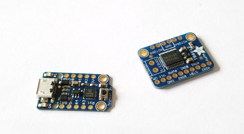
The next step is to reduce the hardware size so that we can reposition it inside of the toy body. For that we will use a trinket 3.3V and a TB6612 H-Bridge motor shield board.


Comments