Soldering Technique for Through-Hole PCB
- Katrina Siegfried
- Oct 1, 2018
- 3 min read
Through-hole soldering refers to soldering wires or pins to a printed circuit board or a proto-breadboard where the wire or pin is pushed through the hole before it is soldered and attached. This technique is like wire soldering but there are important differences. First, let’s discuss what makes a good solder joint for a through-hole solder.

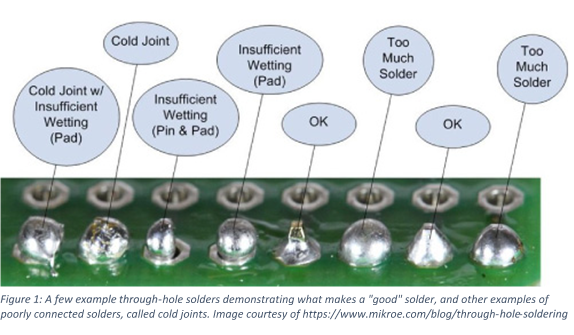
The quality of a through-hole solder is easily deduced from the way the solder joint looks. In the above image there are multiple solder joints. The joints second and fourth from the right are perfect solder joints, notice that it tapers at the base and at the pin, and looks kind of like a circus tent. The other joints are referred to as “cold” joints because they do not properly join the pin and the board, and therefore won’t conduct electricity. Notice how there is not a great connection between the pins and the board on the cold joints. Each cold joint through-hole solder is labeled with the reason for poor connection such as insufficient contact with the pad (wetting) or too much solder.

STEP 1: HEAT UP THE IRON
Heat up the iron to around 650 degrees F, a slightly lower temperature is used in through-hole than with wires because our joints are smaller and too much heat can easily damage the board. Make sure the tip is well tinned.
STEP 2: HEAT UP THE ELEMENTS
Bring the soldering iron to the junction of the pin and the hole as seen in the photo below. Leave the iron in contact for 1-2 seconds to heat the elements up. It is extremely important that the iron is not left to heat the elements for any longer or there is a risk the board will be damaged. DO NOT LEAVE THE IRON IN CONTACT WITH THE BOARD OR PIN FOR MORE THAN 3-4 SECONDS AT A TIME.

STEP 3: ADD SOLDER
Bring the solder to the iron at the junction of the pin and the board and dab it into the heated junction for about ½ second, or just long enough to melt the solder and pull the iron and the solder away. DO NOT LEAVE THE IRON IN CONTACT WITH THE BOARD OR PIN FOR MORE THAN 3-4 SECONDS AT A TIME. If the first attempt is unsuccessful, pull the iron away, wait 10 seconds for everything to cool off, and try again.

STEP 4: CORRECT AND MODIFY IF NEEDED
If the joint is not perfect, this is the time to modify and make corrections. For cold joints, simply bring the iron to the joint again and heat up the solder that is already on the joint for 1-2 seconds or until it flows into the correct formation. If there is not enough solder, repeat steps 1-3 and add a small amount of solder. If there is too much solder, heat the solder up with the iron and drag the excess up the pin away from the joint.
TROUBLESHOOTING
The board has a brown tinge to it and looks a bit burnt.
The brown tinge is from the flux in the solder oxidizing as it heats up. The brown tinge is not in and of itself harmful and can typically be wiped off with a micro-cloth or PCB brush after soldering is finished. Seeing burnt flux should immediately have you questioning the amount of time you are leaving your soldering iron in contact with the PCB, or the temperature of your soldering iron!

The board has a white or black burn mark on it and/or has bubbled up.
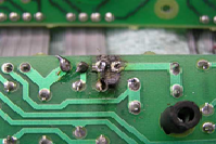
This is bad. This is from the plastic in the board burning from being overheated, and typically happens when the iron has been in contact with the board for far too long and the plastic begins to burn. If this has occurred, it warrants a close inspection of the PCB circuitry and layers to ensure no catastrophic damage has occurred. This is not an easily fixable problem. The image below is courtesy of billmaudio.com and demonstrates why a burnt and delaminated PCB looks like.


Comments