Connected Electric Water Kettle
- Sep 1, 2016
- 4 min read
Everyone has their own morning routines. For me, my morning always starts with a hot cup of tea. This means slogging out of bed into the cold kitchen, turning on the hot water, waiting for the hot water, and a few minutes later pouring my tea. Now, before you start thinking, "Oh my gosh how lazy ARE you?!" know that the project I am about to lay out to you is not necessarily out of necessity, but also curiosity.
The ultimate objective of this project is to connect my electric water kettle to my Amazon Echo for voice control. Below I lay out the process by which I create this project and will update the post as progress is made.
Planning and overall schematic of the project
The end objective is to be able to use voice control to activate various settings on my kettle. This, to me is a bit overwhelming to think about, so I am going to break the main objective into several sub-objectives
1. Identify wiring scheme of electric water kettle
2. Replicate control board with arduino and breadboard
3. Create replica code in C++
4. Connect relay for power cord to Aruino
5. Connect Arduino controls to internet/home-hub
6. Scale down electronics to fit into the kettle assembly (smaller microcontroller?)
Part One: Identifying the wiring scheme of the electric water kettle
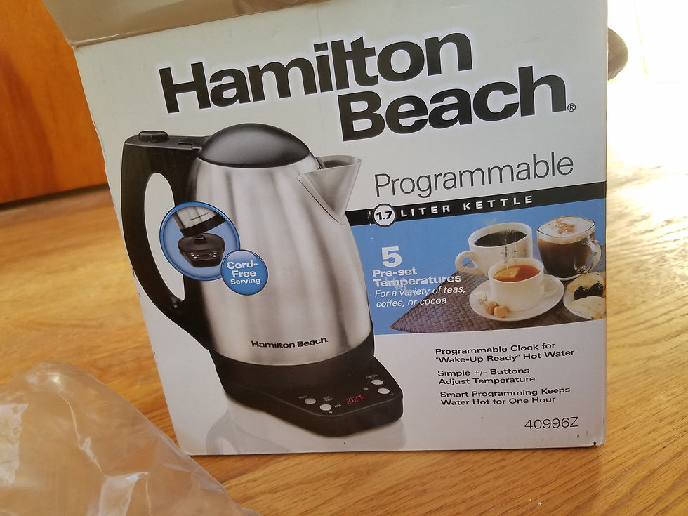
The water kettle I used is a Hamilton Beach Programmable 1.7L Kettle (40996Z). This kettle works well, it has an alarm feature to set a time, on/off, and a preset list of suggested temperatures. The first step is to remove the casing from the water kettle base and determine the wiring scheme in the kettle.
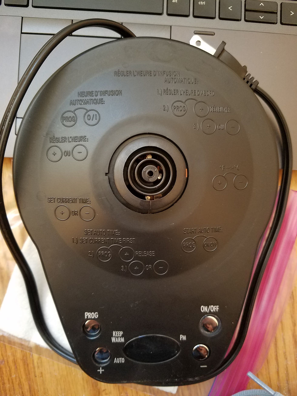
Above you can see a photograph of the base cover which has the instructions for changing settings.
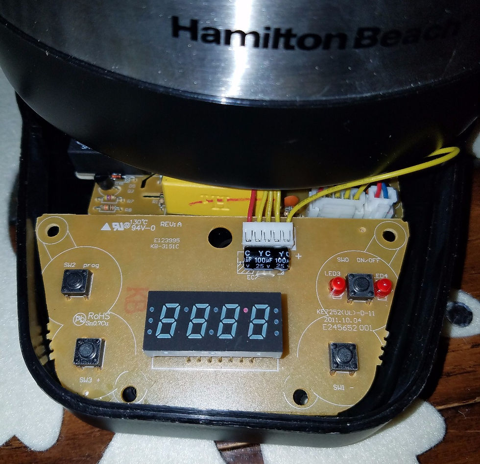
In the image above is the control board (unseated) inside the base of the kettle. Below is a photo of the power circuit board. After examining the internals, it appears that the analog controls for the programming, the buttons, LED's, as well as the digital LED are located on the control board, while all of the circuitry for power regulation are on the power circuit board (this is the board that controls the kettle heating and input from the wall).

In order to determine if this is the proper relationship between the two circuit boards, I tested the voltages of the 5-wire harness that connects the two boards. A fellow DIY'er, Kris Jordan, looks like he embarked on a similar project a couple years ago, but never followed up on his documentation past determining wire voltages. I used his blog post on the PourBot to guide me through this process and confirm my own findings.
The red wire will be wire number R1, and the neighboring yellow wire Y2, and so on.
R1: Positive (5V)
Y2: Ground (0V)
Y3: Thermistor Input (variable voltage input with temperature)
Y4: Switch threshold (2.5V)
Y5: Power Relay Input (0V, 5V)
The power circuit board looks like it is pretty complicated and uses high voltages. It is probably advantageous to leave this alone as it likely has hardware fail-safes to prevent fires. This also means that all of the "control" aspects happen at the control board, which is great news! Now knowing what the relative input/output of the kettle is, I can surmise how each predefined kettle program is controlled.
Switching the Kettle Heat Element On
The control board likely sends a signal to a transistor/relay which then turns on the heating element. This also triggers a count for 60 minutes before auto-shutoff. The 2.5V is likely used as a switch threshold.
Switching the Kettle Head Element Off
The control board likely sends another signal to a transistor/relay which turns off the heating element; this occurs either when the thermistor sends a 0V signal (the kettle is not on the base) or the auto-timer has elapsed.
Programmable clock
Using the push buttons on the control board you can set the clock. This in turn is used to set program alarms. The clock is likely controlled using a counter function (like millis?) The set alarms are likely executed using IF or Case loops.
One hour Automatic Shutoff
Similar to the clock, the one hour shut-off is likely a count-down function and is initiated when the thermistor hits a particular voltage associated with the desired temperature. Probably an IF or Case loop.
Preprogrammed Temperatures
The pre-programmed temperatures are likely determined by an associated voltage from the thermistor.
Part 2: Replicating the control board with an arduino and breadboard
When I looked at the control board closely, I realized that I could replicate this very simply with a microcontroller and a breadboard pretty easily. I already had all of these components laying around too. This would allow me to work on the programming for the microcontroller without altering the control board in any way (so if this doesn't work I am not ruining my kettle). Additionally, it will allow me to side-by-side compare my controller versus the control board that came with the kettle. All of the following components, with the exception of the electrolytic capacitor and wire-harness, came with an Arduino starter kit.
Materials:
- Microcontroller (I have an Arduino, it's likely overkill)
- 2 Red LED's to indicate Power
- 4 Analog push buttons
- Analog LED display
- Jumper wires
- 100 uF 25V electrolytic capacitor
- Wire harness/ headers
- Breadboard
Below is an image of the (mostly) assembled breadboard copy. The next step involves connecting this breadboard to the arduino and constructing the code.


Comments